Content:
- Assemble your Mini-ITX Ironclad Plus
- Board Layout and Internal Connectors
- Front Panel Header
- Fan Headers
- Measures and Choosing a Case
- The Power Supply
- Operating your Mini-ITX Ironclad
- Remote Control and Remote Learning Feature
- Configuration Options
- The “Audio-Exp” header, how to connect your I2S Audio DAC
- The “Massive Heatsink” Installation
- Troubleshooting
Assemble your Mini-ITX Ironclad Plus:
For Ironclad Plus models with any or all SOLID PCB bridges, follow the assembly instructions in the following LINK For the current model with all flexible bridges, continue reading.
This operation must be done in a well illuminated room so you can be sure each pin of every connector goes where it sould.
Needed tools: Philips screwdriver, pliers.
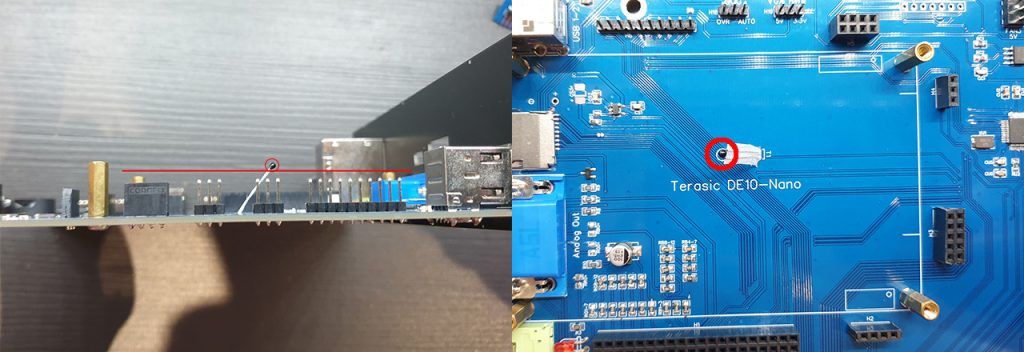
STEP 1 – Screw the provided four standoffs where the DE10-Nano will sit, and check the temperature sensor of your Ironclad, during packaging it has been probably flattened down against the board. It should have its head slightly higher than the standoffs and be bent to the left to be aproximately over the circle mark painted on the board. This is to ensure proper contact with the DE10-Nano from below to have good temperature readings.
STEP 2 – Remove all screws and standoffs from your DE10-Nano fpga board, it must be completely naked, except for the SDRAM module if you are going to use it, if it is not already mounted, mount it now.
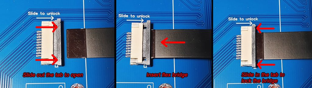
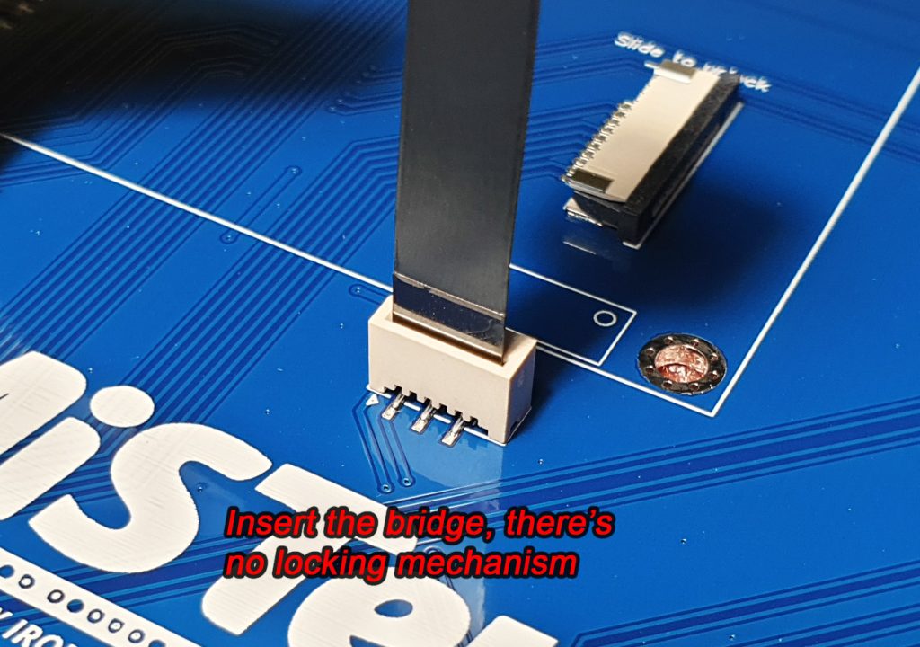
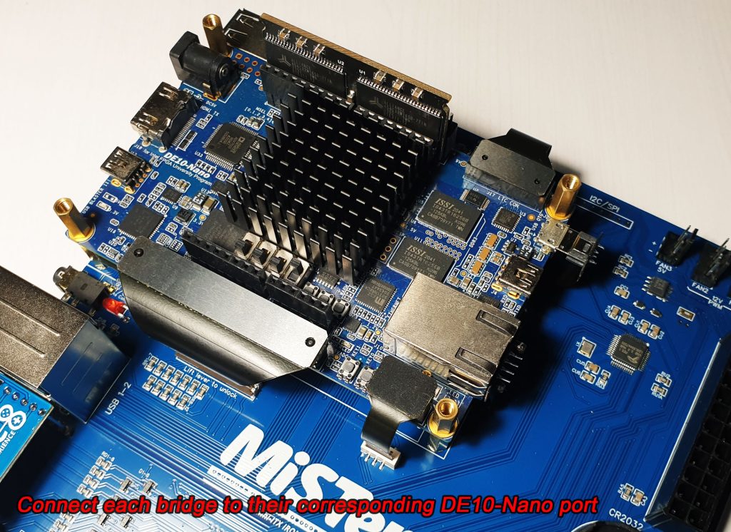
STEP 3 – The Ironclad Plus comes with 5 flexible bridges reinforced with stainless steel and FR4 where aplicable. First insert the bridges into their corresponding receptacle in the Ironclad Plus PCB, in no special order, following the next guidelines:
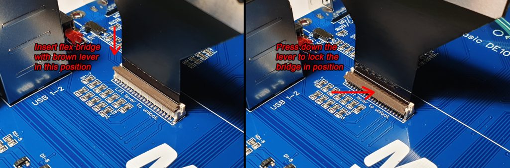
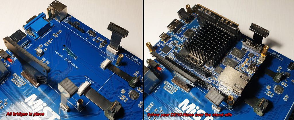
You can disconnect all bridges from the DE10-nano to take it out if necessary, bridges don’t need to be disconnected from the Ironclad PCB anymore if you don’t want to 😉
Put special attention to the Micro-USB port, as you may know the micro USB port on the DE10 is one of its weak spots, don’t put excessive force when plugging, you can see in the picture above, for reference, how much the male connector enters into the DE10-nano receptacle. IMPORTANT: when disconnecting the USB bridge, carefully pull from the micro-USB connector itself, not just from the flexible pcb, to avoid damaging the flexible bridge.
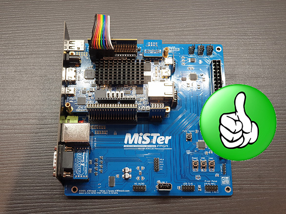
STEP 4 – Connect the supplied ribbon cable as shown in the pictures, over your SDRAM module, paying attention to connect it to the correct pins on the DE10-Nano. Gently insert both ends to the very end.

STEP 5 – Unscrew the VGA and DB9 ports nuts, be careful as the shieldings from that connectors might fall off, with them in place, align and put the backplate in its place and screw again the nuts.
And that’s it!, it took less than 2 minutes, now the whole “block” installs in your case as you would do with any standard Mini-ITX PC motherboard.
Some really small cases force you to introduce the motherboard at an angle to fit, in those cases you might need to unscrew the Ironclad’s backplate, put the backplate into the case from the inside, and insert the Ironclad at the required angle while holding the backplate in place with your hand from the outside.
Board Layout and Internal Connectors:

Front Panel Header:
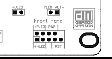
PLED: Connect your case’s “power led” in this two pins. Positive lead is the left one, sometimes it is hard to identify the polarity looking at the cable, if it does not light up, is the other way around.
PWR: Power switch cable from your case goes here, polarity does not matter.
HLED: Connect your case’s “HDD activity led” in this two pins. Positive lead is the left one, if you nailed the PLED, this time there is more probability of failing ;p
RST: Reset switch cable from your case. Many modern cases do not have this, don’t worry if that’s the case, Reset function can also be accessed from the “power” button.
ULED: User led output, you can directly connect here an LED which would make the function of the “Official MiSTer USR LED”. It does not have any other purpose.
PLED_ALT: If you are using your Mini-ITX Ironclad without the GPIO1 bridge, in order to use dual SDRAM modules for example, connect your case’s “power led” to this two pins instead of the main PLED pins. This time positive lead is the right one. In “Dual SDRAM” mode, as the GPIO1 bridge is not connected, the onboard Reset/OSD/User buttons functionality will not work.
The layout have changed a bit with different revisions of the board, but description names and functionality are the same.
Fan Headers and Fan Control Modes:
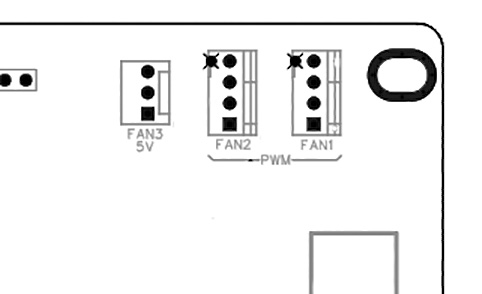
The Mini-ITX Ironclad Plus has three fan headers, the one labeled “Fan3 5v” is designed to always output 5 volts. It is useful if you want to use a 5 volts fan, or a 12 volts fan at reduced speed. You can connect 2 or 3 pins fans here. The speed of this fan cannot be controlled. You can also use this header to connect 5 volts accessories, like led strips, hard disks, or whatever you want.
The other two fan headers labeled as Fan1 and Fan2 allow automatic or manual control of the speed. In order to use this functionality the fans must have a 4 pins connector, 2 or 3 pins fans will not be controllable. This header can also be used to plug LED strips or other 12 volts accessories you like… and your PSU can manage.
Controlling PWM fans: The button on the board labeled as “Fans Control” is in charge of controlling how the fans work, by default your Ironclad Plus comes configured in “Automatic” mode. In this mode the Ironclad tries to keep your FPGA temperature below 60ºC while doing as low noise as posible, if for some reason you are not satisfied with how this performs in your personal setup you can use the “Fans Speed” button to set the fans fixed at your desired speed. It works as follows:
Every time you click that button fan speed cycles between 20%, 30%, 40%, 50%, 60%, 70%, 80%, 90% ,100% and then goes back to 20% and so on. 20% is the minimum the PWM fans standard guarantees to work fine.
To return to “Automatic” mode, press the “Fans Speed” button for 2 seconds, you will hear a double confirmation beep coming from the speaker and the fans go to this mode. If you press the button one more time, the fans return to manual mode with the speed you had previously configured while in this mode. Your manual fans speed and/or automatic mode configuration is saved to memory so the setting is never lost even if you completely unplug your Mini-ITX Ironclad plus.
Measures and Choosing a Case:
The Mini-ITX Ironclad Plus has a standard Mini-ITX form factor, which is 17x17cm (LxW), and 4.8 cm height with the I/O backplate in place, this means it will fit in any standard Mini-ITX case. There are some cases labeled as Mini-ITX which has a height inferior to 5 cm, this cases are badly labeled, as they are Slim Mini-ITX form factor instead and the Ironclad Plus will not fit, so make sure the case you choose has >5.5 cm height. It might be possible to make it fit in one of those “slim” cases, but you will not be able to use the included backplate and/or some modding might be needed, but that is up to you 😉
The Power Supply:
Some cases come with their own power supply or can be bundled with it, that’s the easiest way, but if the one you really like the most does not come with one, don’t despair, ATX power supplies are very common and inexpensive this days, specially when you need a low power one.
The Mini-ITX Ironclad Plus is compatible with PSUs that comply with the ATX standard that use the 20-pins or 24-pins connector, so almost any would do, but there are some minimum requirements to keep in mind.
A fully assembled Mini-ITX Ironclad Plus only pulls about 9 Watts from the wall while running heavy MiSTer FPGA cores, that’s a very low power consumption compared with ATX power supplies everywhere providing 160+Watts!, Ok, that’s true, but the usual DE10-nano power requirements still apply here and it needs a PSU capable of providing about 2 amps from the 5 volts line, just like the PSU that came with it, or even more Amps if you are going to use high power consumption USB devices, like big mechanical hard disks for example which might need another 2 amps just for themselves to start spinning.
Fortunately that 2 amps are a piece of cake for most ATX power supplies, for example, the typical 80 W Pico-PSU provides 6 Amps at its 5 volts output:
picoPSU-80 DC/DC PC ATX power supply (Fanless, 80 Watt) [ PicoPSU ] (cartft.com)
So it is pretty easy to choose a PSU for your Ironclad Plus, if you can see its full specs go to the 5v output and check how many Amps it can provide, if not, just pick one in the range of 120-160 Watts which is plenty of juice and i have never seen one which does not greatly exceeds the 2 Amps from the 5 volts outputs.
TIP: This power supplies usually come with additional connectors, like 4 pin molex for hard disks and floppys, sata power connectors, 4 pin CPU connector, etc. Those connectors have no use in your MiSTer Mini-ITX Ironclad setup, if you know you are not going to use that PSU for other setup in the future, you can just cut them out from their wire’s base while it’s completely unplugged from the wall to make your build cleaner.
The power “brick”: This small PSUs usually come with an external 12v power “brick”, if that is your case, just use that, if you have to purchase one or have one of them at home, 12 volts with 2 Amps at the output is more than enough for the usual MiSTer Mini-Itx Ironclad setup.
Operating your Mini-ITX Ironclad:
Congratulations!, now you have the MiSTer setup of your dreams assembled, now it’s time to know how to operate it ;). The Ironclad has built in buttons for “Menu (OSD)”, “Reset”, and “USR” functions on the PCB, but they are only there for testing, or use in some special cases as you can trigger their functions using just the power button of your case as follows:
- When the Ironclad is OFF, press it to power ON your MiSTer. Pressing it normally will boot normally, pressing it for 2 seconds will make it boot without the “beep”, useful if someone is sleeping next to you 😉
- When the Ironclad is ON, press it briefly to trigger the “Menu (OSD)” function, do a double click to trigger the “Reset” function, or do a triple click to send the “User (USR)” command to your MiSTer. Reset and USR triggering method can be swapped, see “configuration” section below. In dual SDRAM configuration this commands do not work and should be accessed through MiSTer menu using your keyboard or gamepad.
- To turn off your MiSTer press and hold the power button for two seconds.
If your case happens to have a Reset button, and you connected it, you can use it to directly trigger a “Reset” command with a single press, or completely power cycle your MiSTer by pressing and holding the button for 2 seconds.
Remote Control and Remote Learning Feature:
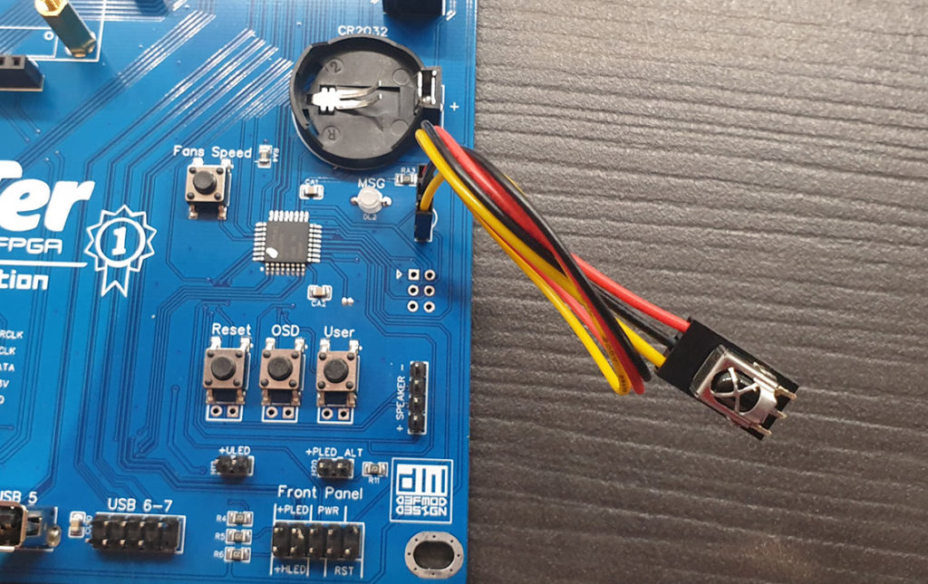
Connect your receiver to the Ironclad using this picture as a reference:
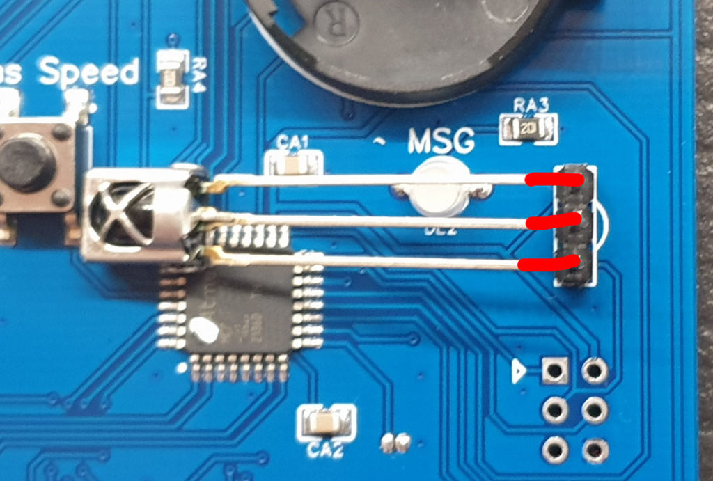
Recently the header for the IR receiver has been moved to the front panel header, next to the “RST” pins, same principles apply, check the small onboard diagram to know the correct receiver orientation.
Use the supplied 20 cm extension cable to mount the receiver wherever you like in your case. Cut the legs and bend them backwards if necessary to make it fit in tiny spots. Drill a small 4 mm hole, and fix the receiver from the inside with hot glue or any non-conductive sticky stuff.
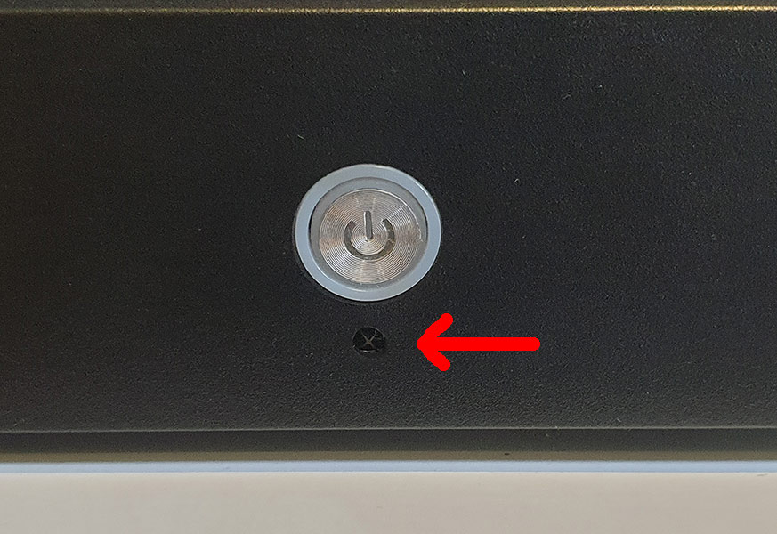
WARNING!!: This receivers are pretty sensitive to reverse voltage and they will kill themselves immediately if that happens by mixing pin connections or if the metal housing touches any other signal different than “ground”, it can touch the chassis of the case though, so pay extra attention to connect it following the correct pin correspondence and don’t let it dangling around inside the case. If it breaks you can purchase a replacement from Amazon or your local electronics shop, they are very common and inexpensive. The model number is VS1838B, any 1838 will work, but make sure it has the metal shielded “head”.
Remote Learning procedure: With the Ironclad in “standby” mode (with red led) press and hold the “fans speed” button on the PCB for 2 seconds and release it, you will hear a beep, point your remote to the receiver and press the button you want to function as power on/off, if the code is recognized you will hear two beeps, then press the button you want to be “Reset”, if OK you will hear three beeps, then the button you want to be “Menu (OSD)”, you will hear four beeps, and finally press the button you want to be saved as “USR” command, you will hear a “melody” and the commands are saved. If you have the Internal MT32-Pi hat connected using the onboard “Pi-CONN” header, two additional remote commands are requested to learn after the USR command, they are “rom” and “synth” for the MT32-pi, then the final melody will be heard.
If you are in the middle of the learning process and no valid remote control command is received during 20 seconds or you press the case power button, the learning process is cancelled and an “error tone” is played. No changes are made to the previously saved remote commands when the process is timed-out or cancelled.
Configuration Options:
By default “Reset” function is triggered with a double click of the case power button, and “USR” command is triggered with a triple click. In some situations you would want it to be the oposite way, for example; if your case has a dedicated reset button, if you are used to never use the reset command at all to go back to the main MiSTer menu, or if you happen to trigger some undesired resets while trying to perform a “USR” command. To change this behavior and have “USR” with a double click and “reset” with a triple click instead, do three clicks in the “fans speed” button on the PCB while the Ironclad is ON (green led), you will hear an acknowledge tone and the setting is saved. Do it again if you want to change that around again.
Silent mode: This feature is only available on current board models with the buzzer soldered on board, click on the “Fans control/Config” button 5 times to toggle “Silent mode” no matter if it is on or off. In this mode beeps on powering on, off, and reset will not be heard until you manually toggle again this mode. There is also a temporary “silent mode”; if you turn on your Ironclad Plus with a long press of the case power button it enters temporarily into this silent mode and no beeps will be heard for that session, once you turn it back off it returns to standard beeping operation.
Cabinet power mode: In this mode your Ironclad Plus will turn on as soon as it receives power, which is ideal for operation inside an arcade cabinet without needing to modify or hack your power supply. This function is only available in recently manufactured boards. To toggle this mode click on the “Fans control/Config” button 7 times while the Ironclad Plus is ON (green led).
Factory Reset: With the Ironclad in standby mode (red led), click 10 times on the “fans speed” button on the PCB. This resets all configurations to factory defaults, which are; fans speed / mode, remote control codes, button commands, and everything. This might be useful for troubleshooting, or if you lose a remote you had saved, and want to return to the default factory remote control buttons.
Disable all thermal capabilities: With the Ironclad in standby mode (red led), click 14 times on the “fans speed” button on the PCB. This feature is something one normally shouldn’t use, but in case the thermal sensor on the board gets ripped apart by accident, you can use this command to disable every function relying on it. In this mode the Ironclad will not enable the automatic fan control, will not warn you when it reaches certain temperatures and will not turn itself off when it thinks the temperature reach 80 degrees C. This option is saved and can only be reverted if you do the command again or do a factory reset.
The “Audio-Exp” header, the Hi-Fi Blaster, and how to connect your I2S Audio DAC:
Thanks to the modular design of the Ironclad Plus and its future proof design, the “Audio-Exp” header allows to improve the audio quality of all analog audio outputs at once, for true retro-audiophiles. It was designed to connect the Hi-Fi BLASTER module, also developed by myself, which offers enhanced audio quality plus true amplified headphones audio output for your case headphones jack, all fine tuned for the Ironclad Plus and MiSTer’s audio signal, check it out in depth HERE , but you also have the option to use any other I2S Audio DAC of your choice, no modding to the Ironclad Plus is required, just connecting the module following this diagram:

To do that, for example, you can solder a pin header to the I2S DAC module of your choice and use dupont cables to interconnect the pins to the “Audio-Exp” header, don’t forget bridging the two pins in the diagram. Beside connecting the module, you also need to flip the “SW0” switch on your DE10-Nano to enable I2S audio, it is the rightmost switch. The “Audio-Exp” header is disabled while in dual SDRAM mode operation and no audio module connected here will work.
The Massive Heatsink Installation:
The Massive Heatsink installation is easy, but it is recommended to follow some guidelines to avoid future issues when fitting more stuff over your DE10-nano. The double side thermal tape is pretty strong, and removing it afterwards to correct the installation may cause the heatsink to break by separating the copper core from the aluminum fins.
First present the heatsink next to the DE10-nano, the copper core is not centered on the heatsink and it must be oriented to the top to match the FPGA location, before peeling the blue protector practicing the correct positioning is highly recommended.

The next image shows the optimal positioning, use the bottom four metal switches (SW0-3) and the top black female header as reference points. The heatsink should be touching the switches shielding from the top, and aligned in line with the right side of the top female header. When you are ready, remove the blue glue protector and place it in its final position.

Troubleshooting:
The built in BIOS is always actively taking care of your DE10-Nano, it is an expensive piece of hardware nobody wants to put at risk, the main culprit of most failures is the power supply not working as it should or giving voltages way out of specification, if you experience sudden shutdowns or sudden shutdowns followed with 3 beeps from the piezo speaker, then probably the problem is the power supply voltage rails are suddenly shutting down or fluctuating to dangerous levels and the Ironclad Plus is turning off power to prevent damage. If the sudden shutdown is followed by 5 beeps, then there is something wrong with your DE10-nano installation or it is failing to work reliably, if it is installed correctly and this 5 beeps error continues, it might be the PSU is not providing enough power to keep up and the DE10-nano is being deprived of enough juice causing resets and reboots. Trying with another PSU would be the first step.
The Ironclad Plus BIOS also does various checks at power on, like your computer does, if something is not right it will emit tones through the piezo speaker, indicating the following possible ERROR CODES:
- 3 Beeps: PSU is not responding to the Ironclad’s tries to turn it on, or voltages provided are out of spec and damage might be caused in case of feeding that to the DE10-nano. Check if the PSU is correctly connected, there are no shorts or peeled cables, or try with another PSU.
- 5 Beeps: PSU power rails seem OK, power is being provided to the DE10-nano, but the DE10-nano is not responding. This error is usually caused by a bad installation of the bridges. In case of Single SDRAM module operation the only mandatory bridge is the big GPIO one, in case of dual SDRAM operation mode the RTC and ADC bridges must be connected or you will have this error. If that does not fix it, then check if your DE10-nano is working by itself outside of your Ironclad, and if it does, the problem might be in the bridges themselves, or the ATX PSU.
Sluggish operation in general, huge delays in button presses, continuous beeps and weird tones from the piezo speaker: Try resetting factory defaults, or doing the “disable thermals” command.
In the rare case there is any other failure not described here, the first thing to try would be disassembling everything, plugging the Ironclad Plus naked board, with no DE10-nano or anything else attached, to your ATX PSU, and having at hand a flat screwdriver in order to bridge the “PWR” pins to simulate presses on the case power button. If after plugging the PSU there’s no RED led, and there are no beeps coming from the piezo speaker after momentarily bridging the PWR pins with the screwdriver, then something important broke and that board might need repairs or replacement, please contact me via e-mail, and i will give you further instructions and look at your individual case.