This instructions are only suitable for Ironclad models that came with at least one bridge made of solid PCB.
Assemble your Mini-ITX Ironclad Plus:
This operation must be done in a well illuminated room so you can be sure each pin of every connector goes where it sould.
Needed tools: Philips screwdriver, pliers.
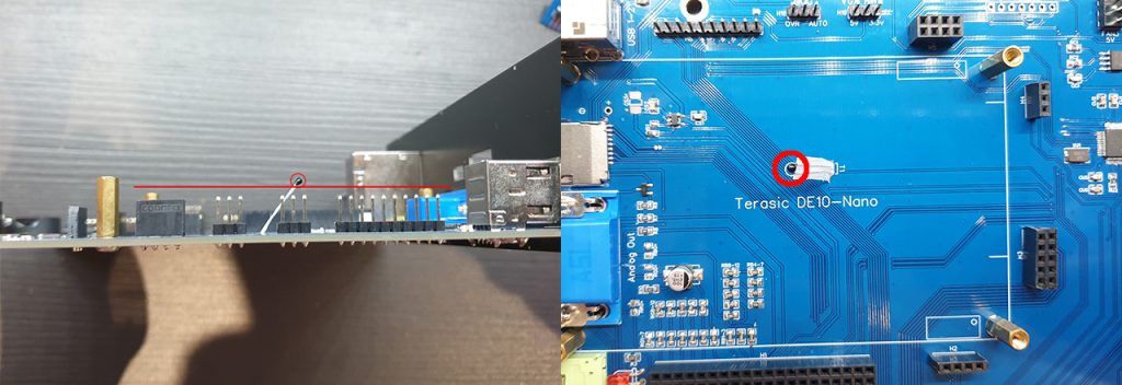
STEP 1 – Screw the provided four standoffs where the DE10-Nano will sit, and check the temperature sensor of your Ironclad, during packaging it has been probably flattened down against the board. It should have its head slightly higher than the standoffs and be bent to the left to be aproximately over the circle mark painted on the board. This is to ensure proper contact with the DE10-Nano from below to have good temperature readings.

STEP 2 – Remove all screws and standoffs from your DE10-Nano fpga board, it must be completely naked, except for the SDRAM module if you are going to use it, if it is not already mounted, mount it now.
STEP 3 – Insert first the Ethernet and Micro-USB bridges to the corresponding DE10-Nano ports.

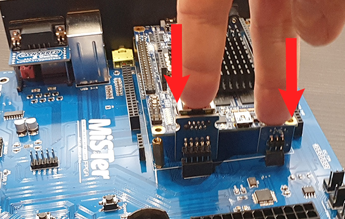
STEP 4 – Put the DE10 over the stand-offs on the Ironclad in the correct orientation and connect both bridges to the ironclad while inserted into the DE10 by pressing gently from the top of the Ethernet and Micro-USB ports themselves using two fingers at the same time, not by pressing anywhere else on the DE10 board, this is to ensure the Micro-USB connector does not suffer any stress as it is the weak spot here.

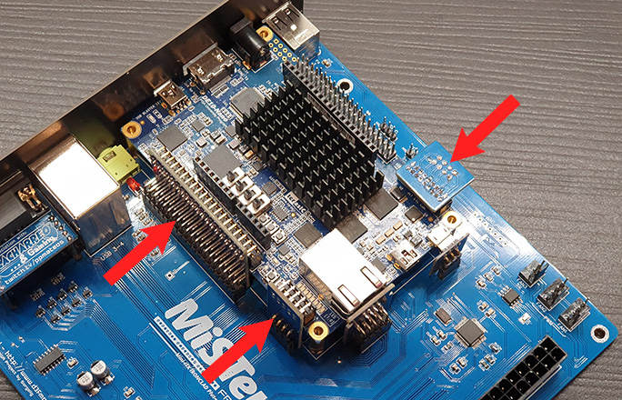
STEP 5 – Connect the rest of the bridges; the RTC, the GPIO, and the ADC in their corresponding places by inserting them from top to bottom. As the female connectors are on the Ironclad and the bridges are males, you can very easily see from the top when the pins are going to the correct places, please pay special attention to this.

STEP 6 – Screw the DE10-Nano to the Ironclad’s four stand-offs using the original screws, or stand-offs, that came with your DE10-Nano, you can also use standard small floppy/hdd/ssd computer screws.

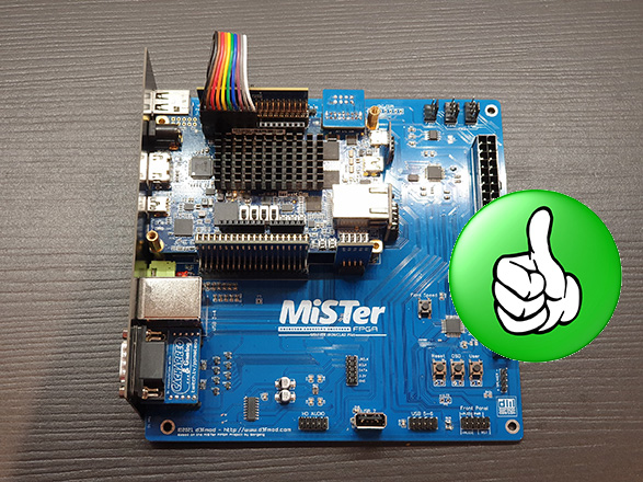
STEP 7 – Connect the supplied ribbon cable as shown in the pictures, over your SDRAM module, paying attention to connect it to the correct pins on the DE10-Nano. Gently insert both ends to the end.

STEP 8 – Unscrew the VGA and DB9 ports nuts, be careful as the shieldings from that connectors might fall off, with them in place, align and put the backplate in its place and screw again the nuts.
And that’s it!, it took less than 2 minutes, now the whole “block” installs in your case as you would do with any standard Mini-ITX PC motherboard.

Some really small cases force you to introduce the motherboard at an angle to fit, in those cases you might need to unscrew the Ironclad’s backplate, put the backplate into the case from the inside, and insert the Ironclad at the required angle while holding the backplate in place with your hand from the outside.
UPDATE!: Newer Ironclad Plus revisions include one or two custom made black flexible bridges, they are softer, easier to install and remove, installing them is pretty straight forward, but here are some guidelines:
First, bend the bridge as shown in the picture, you don’t need to be precise, this is just to make the alignment over the connectors easier. Don’t bend the flex bridge to a sharp corner or put excessive force.

Put the bridge over the connectors and present it to make sure it is correctly aligned, then press it down in its place making sure it is inserted completely, specially the bottom part which has the shorter pins, and that’s all.

To remove this type of bridges, lift carefully first the bottom part, and then the top part. When disconnecting use your fingers to pick the bridge from both sides of the connectors, not the flexible, to avoid possible damage to the bridge.